
Calibrating your Resistor Ladder Aux Switch
Overview
The Resistor Ladder Aux Switch feature for the Omniport allows you to connect up to 8 (for the MC3/MC6MKII/MC8) or 16 (for the pro series) external switches using Omniport 1.
We are currently not manufacturing the aux switch but you should be able to find a third party manufacturer.
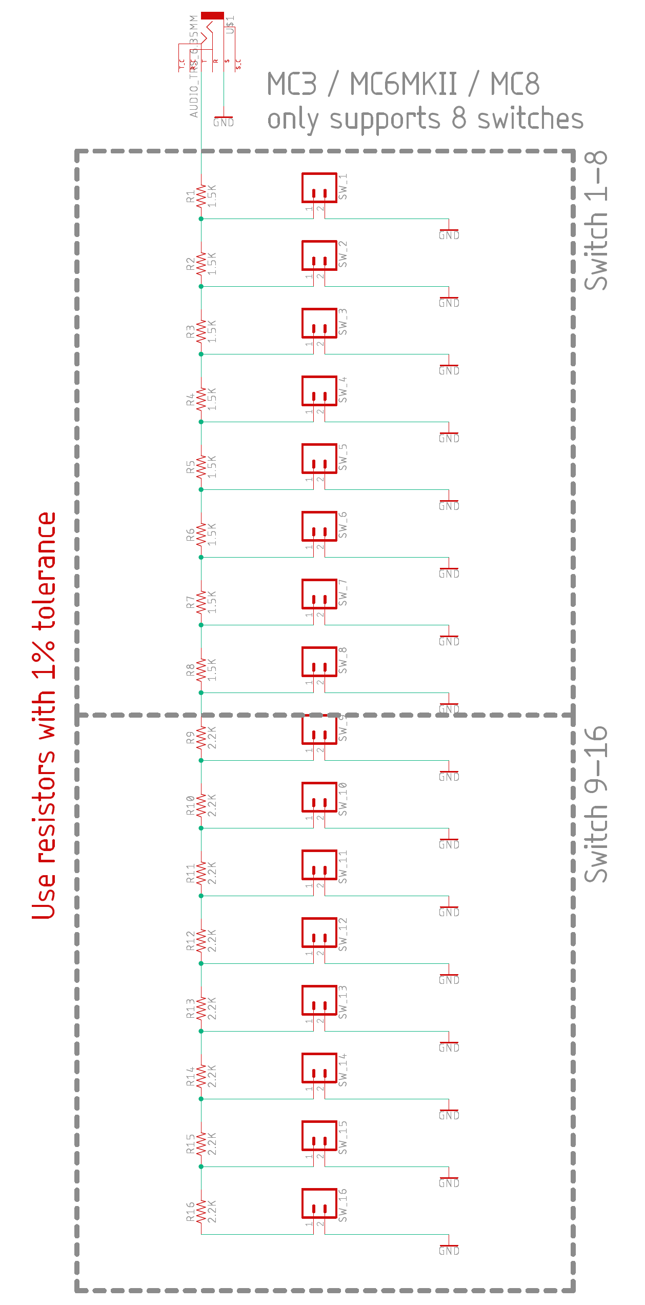
Schematic
The recommend resistor values can be found below. Different values may be used, as long as the controller can read a different value on each switch during the calibration process.
Only the Tip and Sleeve is used in the Omniport. The Ring connection is ignored, so you can use a TS cable with this.
Calibration process
First, connect to the Editor and then set Omniport 1 to Resistor Ladder Aux Switch. Then, save your settings and restart your controller to load the new Omniport settings. The calibration can only be done after the controller restarts.
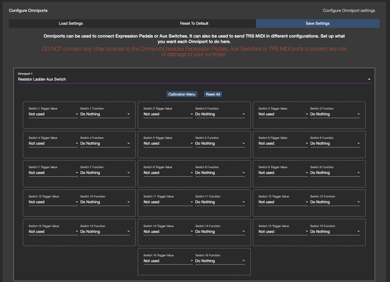
Go into the Controller Settings >> Configure Omniport menu again. Click on Calibration Menu. This will open the calibration menu on the controller, which will display a value based on the resistance it reads.
Next, you can begin the mapping/calibration process. Press and hold down a switch (on your aux switch) to see the resistance value on the controller. For example, Switch 1 displays the the value 11 on the controller. Then, you can map that value to a function in the editor.
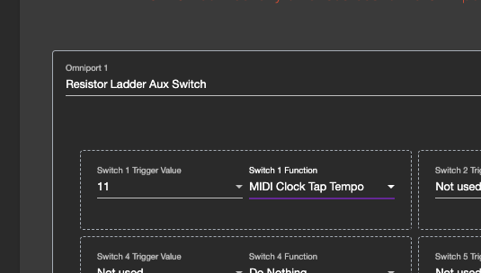
In the example above, I have mapped the trigger value 11 to MIDI Clock Tap Tempo. Pressing on Switch 1 gives me the value 11. So, Switch 1 is now mapped to the Tap Tempo function.
If the value is jittery during calibration (i.e. it shifts between 20 and 21), you can select either value as there is a +-1 buffer for the value. For example, if you have the trigger value set to 20, a value of 19 and 21 will also trigger it.
You can continue this process for the rest of the switches.