
User Manual
Overview
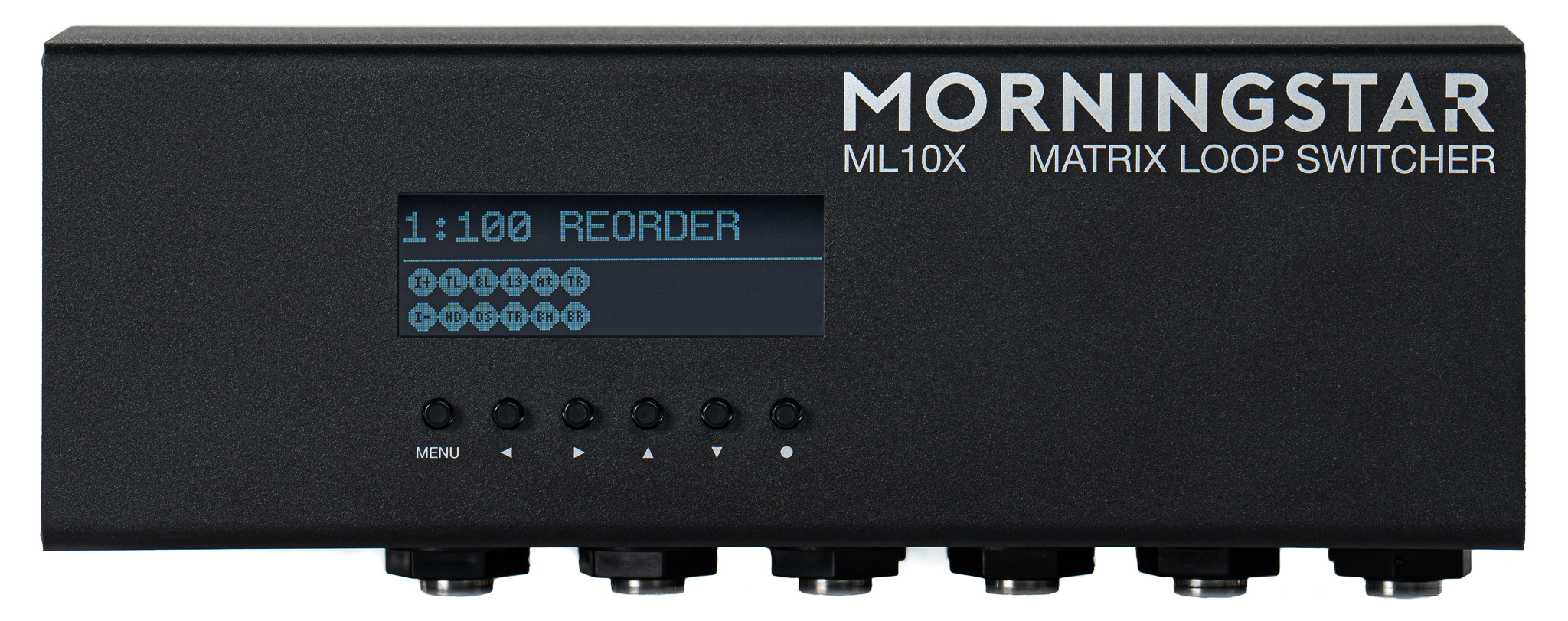
The ML10X is a MIDI-controlled reorderable Loop Switcher.
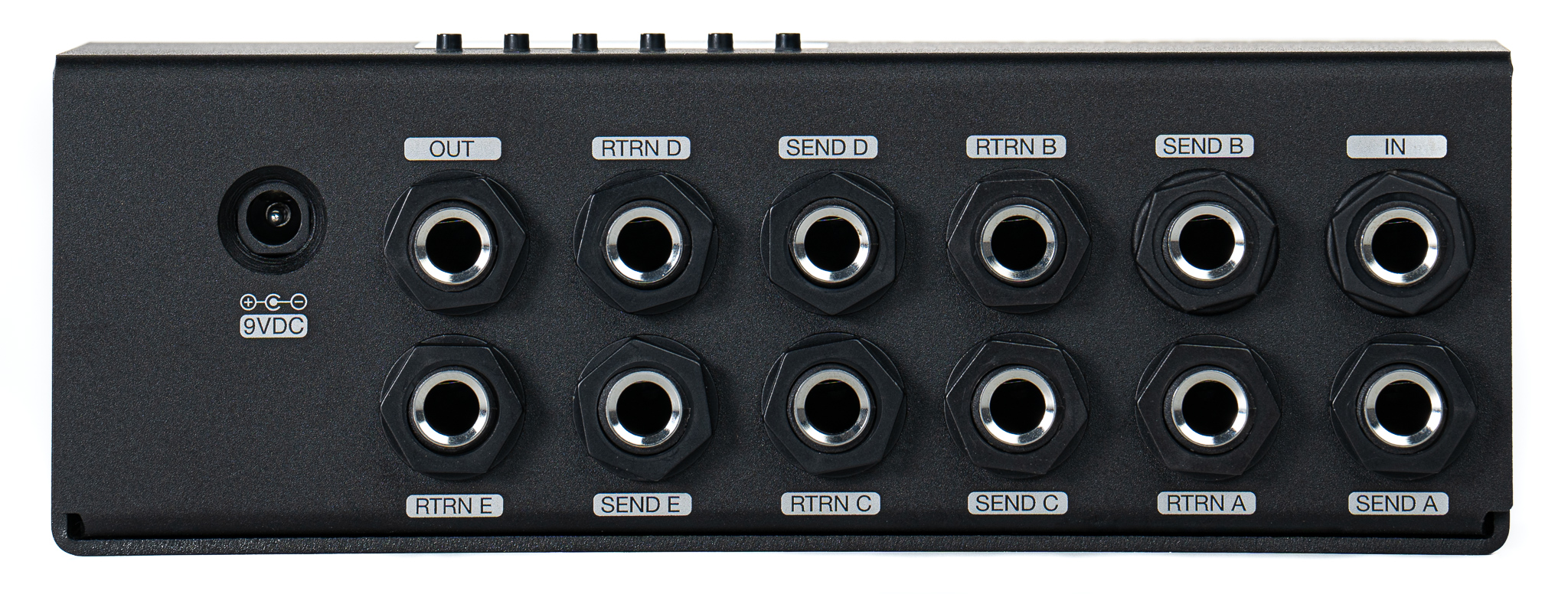
There are a total of 10 independent loops available, configured in 5 TRS send and return ports.
The send and return ports are called Loop A, Loop B, Loop C, Loop D and Loop E. All the ports are TRS ports, which means they take in a Tip and Ring connection.
Each Tip and Ring connection can be programmed independently. That means, you can connect a Distortion pedal to Loop A Tip, and a Delay pedal to Loop A Ring, and then route them to run in series.
For example:Input Tip >> Loop A Tip >> Loop A Ring >> Output Tip
Since the Tip and Ring connections on each Loop can be used independently, that means that you can connect up to 10 devices running in Mono and be able to switch and reorder them.
All the inputs and outputs are buffered.
USB Port
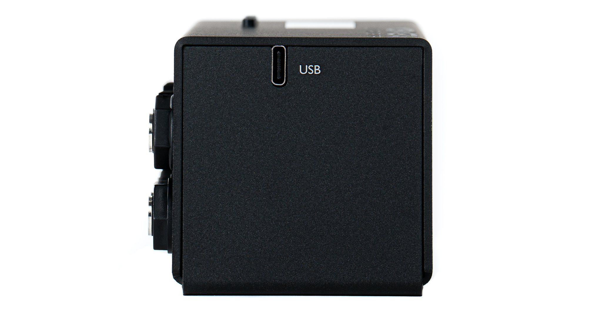
The ML10X has one USB C port to connect the device to the editor in a Windows or Mac computer.
MIDI Ports
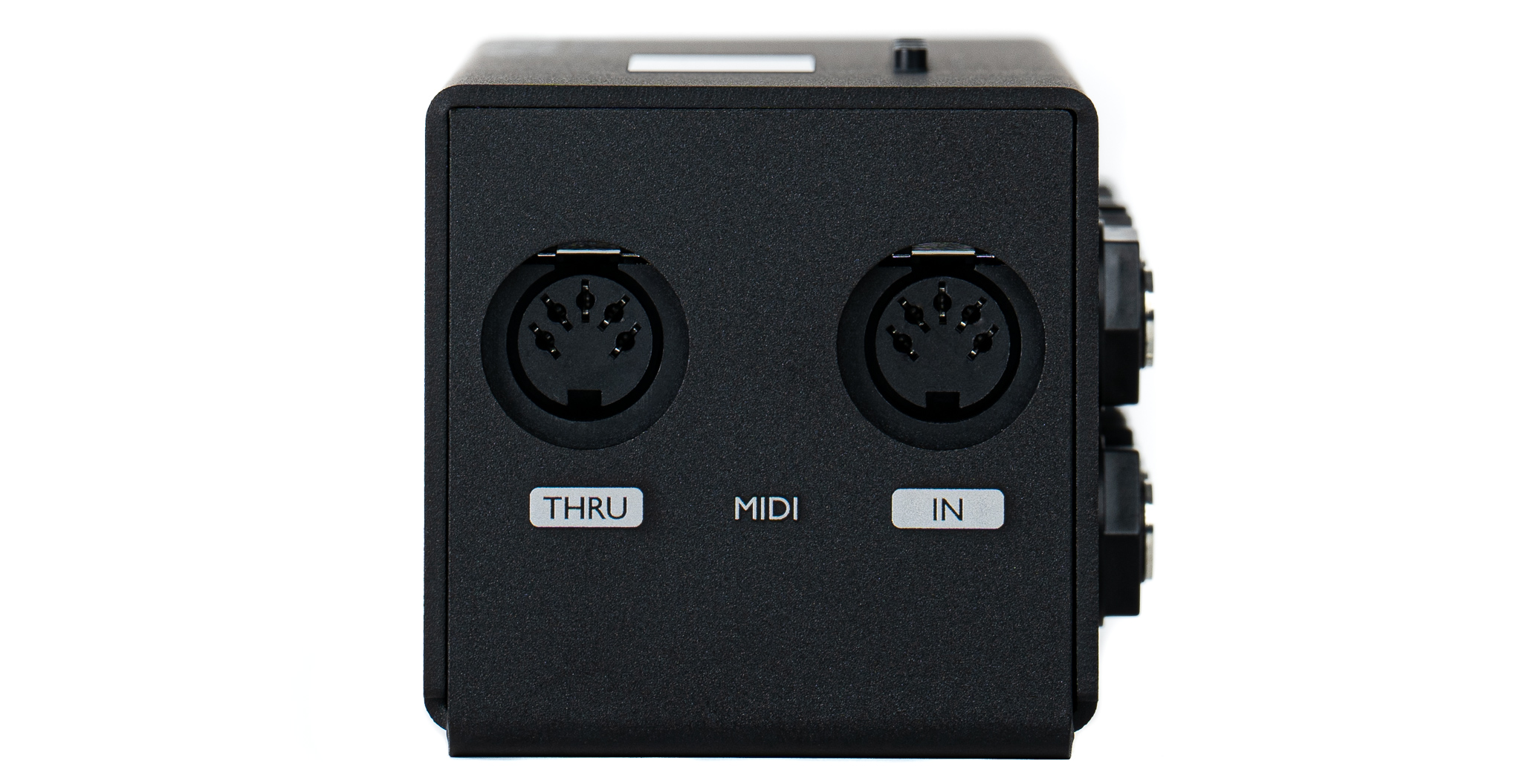
The ML10X has one 5-pin MIDI IN port and one 5-pin MIDI THRU port.
Banks and Presets
The ML10X has 4 Banks with 128 Presets in each bank.
The Preset number start from 0 and range from 0-127.
Power Requirements
9-18VDC Center Negative with at least 160mA current.
If connected only via USB, the ML10X processor will power on and allow you to navigate the device or connect to the Editor, but no switching will occur. To use the device for switching, you will need to disconnect the USB cable and restart the device with an appropriate DC power supply connected.
Other Specifications
Max input level
4v peak to peak (with 9v power supply)
10v peak to peak (with 18v power supply)
Input/Return Impedance: 1M ohm
Output/Send Impedance: Approx 100 ohm
Device Controls
Buttons | Function |
|---|---|
| Scroll up and down presets |
| Bank up and down |
| Scroll up and down presets by 10 |
| Access device menu |
| Change view |
Hold | Quick access to Preset connections menu |
Programming the ML10X
The ML10X can be programmed within the device itself or with the desktop web editor (https://editor-mkii.morningstar.io/ml10x).
Programming within the device itself will only allow you to program a preset in simple mode. If you need to use the advanced mode, you will need to use the desktop web editor to program the Preset.
The ML10X is not designed to be used live with a USB cable connected, due to the potential for ground loops. If you are experiencing any increased noise floor in your rig, please disconnect the USB cable from the ML10X.
Preset Modes
Each Preset has a simple mode as well as an advanced mode.
Simple Mode
Simple mode allows you to create Mono signal chains in the device itself or in the Editor. You can select which loops you want to bypass when a Preset is loaded, and you can control each loop’s bypass/engage status via the CC MIDI Implementation, or, if you have a Morningstar MIDI controller, you can use the ML10X Integration message type for control.
You can also specify what loops to spillover, such that when you bypass a loop or change Presets (simple), the specified loop will route to the output.
Editing a Simple Preset
Advanced Mode
Advanced mode gives you the ability to create complex signal chains, with the ability to split and merge signals.
Loops cannot be bypassed in advanced mode. Please read FAQ for more information.
When a Preset is in advanced mode, the Preset can only be edited in the Editor, and not on the device.
This flexibility comes at the expense of some features:
Loops cannot be bypassed (using CC messages etc).
Spillovers are not automatically created (like in
Simplemode). When a Preset inadvancedmode is loaded, the signal chain will be loaded exactly as how it is created.Preset cannot be edited on the device itself, and needs to be connected to the Editor to be edited.
It is possible to reset the Preset in the device, which will revert it back to
simplemode.
Editing an Advanced Preset
Programming a Simple Preset in the ML10X
We designed the ML10X to be as simple and straightforward to use, and have avoided confusing concepts and nuances that users need to know.
To create a Preset on the ML10X, you just need to link a From connector to a To connector. Want to bypass all the loops? Just link Input to Output. How about having just Loop A in the signal chain? You just need to link
InputtoLoop ALoop AtoOutput
In the first page, the device will prompt you to select a From connector to start. These are the available From connectors:
Input TipInput RingLoop A TipLoop A RingLoop B TipLoop B RingLoop C TipLoop C RingLoop D TipLoop D RingLoop E TipLoop E Ring
Once you have selected a From connector, the device will prompt you to select a To connector to. These are the available To connectors:
Output TipOutput RingLoop A TipLoop A RingLoop B TipLoop B RingLoop C TipLoop C RingLoop D TipLoop D RingLoop E TipLoop E Ring
Examples
Example 1
If you want to get a mono signal flow like this:
Input >> Output
which means that you’re bypassing all the Loops, you just need to link Input Tip to Output Tip, which means that the Input Port (Tip connection) is now connected to the Output Port (Tip connection).
Example 2
If you want to get a mono signal flow like this:
Input >> Loop B >> Loop D >> Output
You will need to link
Input Tip >> Loop B TipLoop B Tip >> Loop D TipLoop D Tip >> Output Tip
Programming a Simple Preset in the Editor
In the ML10X Editor, you can simply drag and drop each loop to create your signal chain.
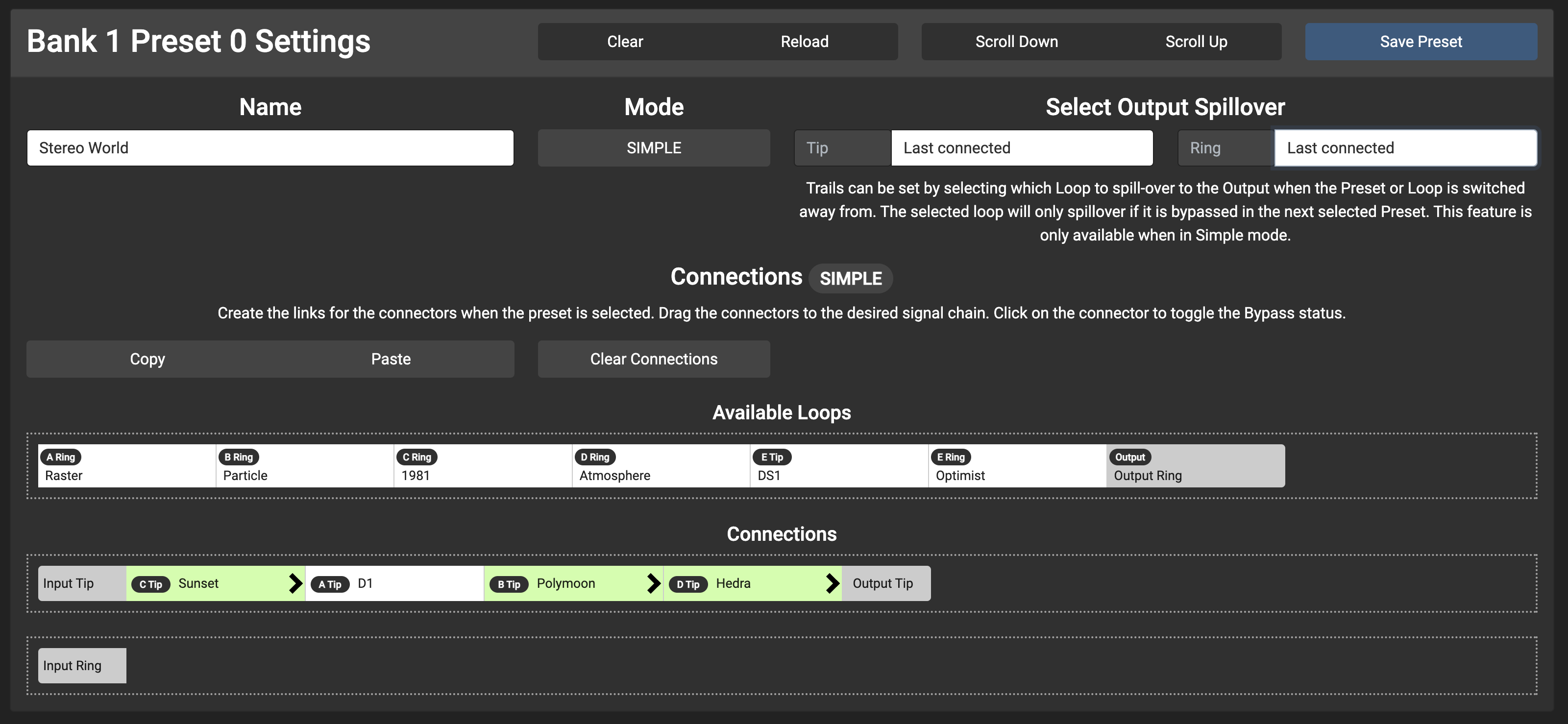
When the loop is Green, the loop will be engaged when the Preset is loaded.
When the loop is White, the loop will be bypassed when the Preset is loaded.
You can toggle between Engage and Bypass by clicking on the Loop name button (e.g. B Tip).
Output Spillover
The Spillover feature allow you to merge signals into your output signal when you bypass a selected spillover loop or change Presets where the selected spillover loop isn’t used in the signal chain.
For example, if you are currently in Preset 1 that has a Delay effect, and you switch to Preset 2 that does not use that delay effect, you can set the ML10X to automatically merge the delay signal into your output so the delay signal does not get cut abruptly.
Example
Your Preset 1 signal chain is as such:
Input Tip >> Overdrive >> Delay >> Output Tip
and your Preset 2 signal chain is as such:
Input Tip >> Overdrive >> Output Tip
When you switch from Preset 1 to Preset 2, you might want the delay trails to continue even though you have switched out your delay.
You can do this by selecting a connector for the Output Tip Trails in Preset 1. If Delay is selected as the Output Tip Trails, when you switch from Preset 1 to Preset 2, your signal chain will be as such:
Input Tip >> Overdrive >> Output Tip
Delay >> Output Tip
A connector can only be used as a trail connector when it is not being used in the Preset you are switching to. For example, if you have a connection as such:
Input Tip >> Delay >> Output Tip
and if you also have the Delay as an Output Trail, the programmed signal chain will take precedence and the Delay will not be used as an Output Trail.
Programming an Advanced Preset in the Editor
To edit a Preset in Advanced mode, simply toggle the Mode button to ADVANCED. The flow editor will appear.
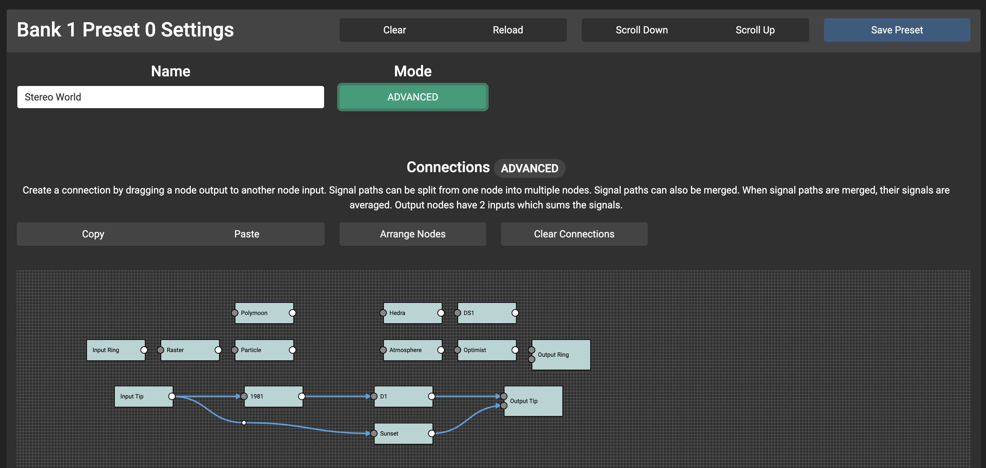
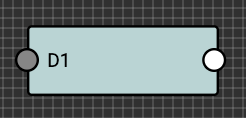
Each loop (or Node) will have an Input and Output, coloured grey and white respectively. The left grey dot represents the send connection, while the right white dot represents the return connector.
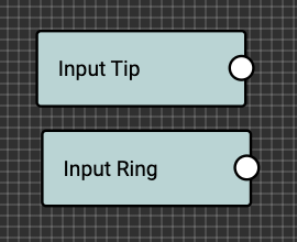
Input nodes will only have a return connection. This represents the audio signal being sent into the Input port, where you can route it to a send connection.
Output nodes have 2 send connections. This represents the audio being sent out in the Output port. There are 2 send connections because the Output port has a built-in audio summing circuit.
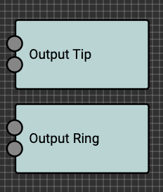
When connected to the same output node, audio is averaged.
When connected to both output nodes, audio is summed.
Summing is useful for creating Presets with spillover effects.
Preset 1 - Overdrive with delay before switching
Preset 2 - Clean tone with overdriven delay repeats spilling over after switching from Preset 1
It can even be used as a volume boost, since the signal is summed.
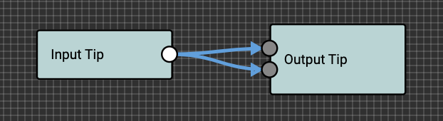
Split signal is summed, creating a volume boost.
Creating connections
To create a connection, simply click and hold an output and then join it to an input.
Deleting connections
To delete a connection, right-click on the connection and then click on the delete button.
Moving Nodes
Drag and drop to move each node.
Connection reroute points
When the Editor auto-arranges the nodes, reroute points may be created automatically on the connection lines to better display the connections. You can move them or double-click to remove them.
Saving Presets
The new connections will only be updated in the device when the Preset is saved.
The exact layout and node positions created in the editor cannot be saved to your device. Each time a Preset is loaded, the nodes are arranged programmatically based on the connections created between each node.
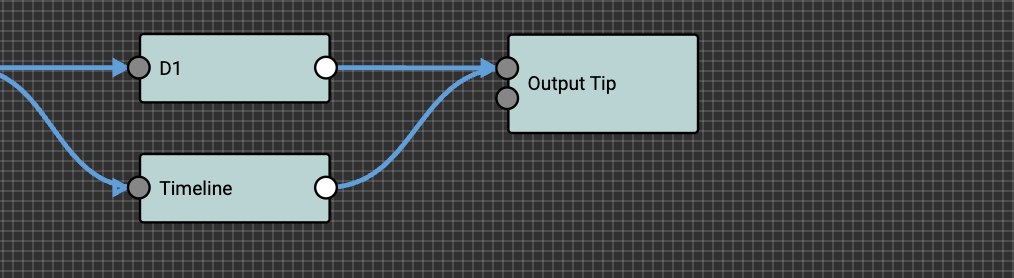
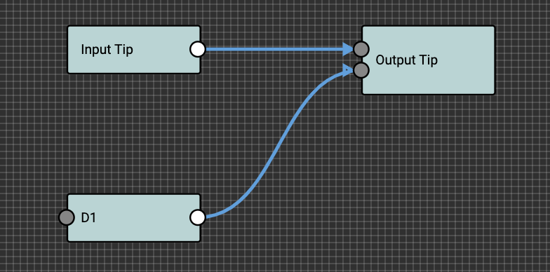
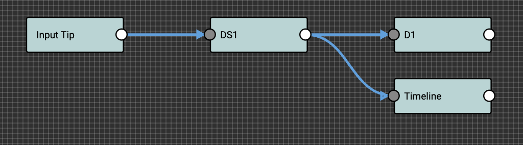
Beware of feedback loops
With such flexibility, you need to be aware of potentially creating feedback loops in your setup. In the example below, there is a feedback loop where the signal coming out of D1 is merged with a split signal from Input Tip. It is also possible for the signal coming out of D1 output to flow back to the D1 input, causing a feedback loop. There will be a feedback noise when this happens.
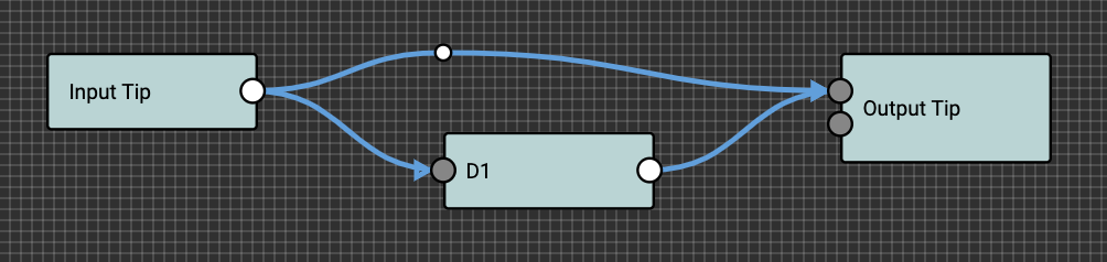
Feedback loop
Splitting Signals
To split a signal, simply connect one node to two or more nodes.
Merging Signals
To merge a signal, simple connect two or more node into the desired node.
When signals are merged, they are averaged out. To explain, a simplistic example would be that if you have two equal signals, S1 at 100% S2 and 100% and are being merged, the merged signal will have 50% of S1 and 50% of S2.
There are no phase inverters and mixers in the ML10X. If you are experiencing signal loss when merging the signals, your signal coming out of one of your devices might be phase inverted. If you need to merge the signals, you can consider using an external phaser inverter to invert the signal coming out of that device.
Creating Spillover Effects
If switching from a different preset into an advanced preset, and you want to create an output trail, connect the desired nodes to the second input on the Output node.
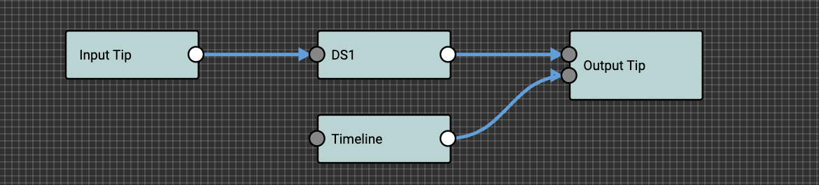
In the above example, the preset will allow the delay trails from the Timeline node to be summed in the Output node.
Connector Settings
Connector Name
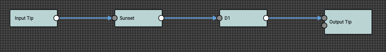
By default, each port is named Loop A Tip, Loop A Ring … Loop D Tip. It is possible to name each port to suit your device for better clarity when creating Presets. For example, you can rename Loop A Tip to Timeline, and Loop B Tip to Meris Enzo, for example, and when you create your Presets, you will see:
Input Tip >> TimelineTimeline >> Meris EnzoMeris Enzo >> Output Tip
Connector Short Name
You can also give a 2 character short name. This will be used in the lineage display if the Preset is in Simple mode.
Editing Connector Names in the Editor
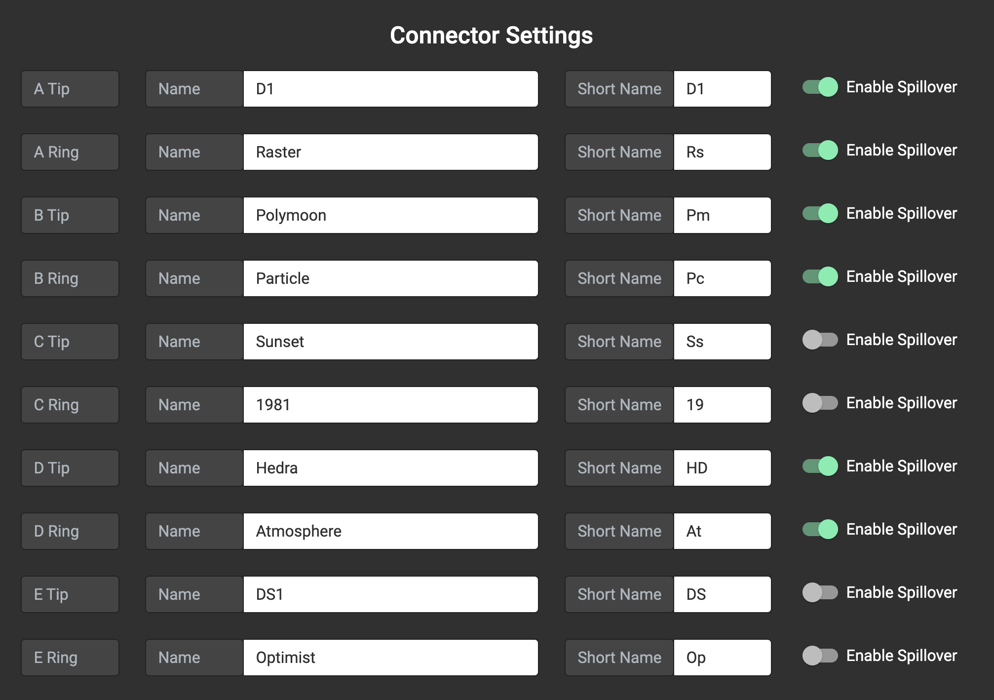
Connector Spillover Settings
You can select whether each connector should be used in the Spillover function in Simple mode. Typically, you would only want to enable spillovers for your delay or reverb effects where there is an audio trail. So, when your Preset Spillover setting is set to Last Connected, only these loops will spillover into the output. You do not want to enable Spillover for high gain pedals, because that may introduce noise into your output even though there is no signal going into the high gain pedal’s input.
Spillover in Advanced mode
The Spillover settings do not apply to Advanced mode. As indicated earlier, when an Advanced Preset is loaded, the connections are loaded as is. If you require spillover settings in the Preset, you’ll need to create the desired spillover signal chain in the Preset and connect it to the second input in the Output node.
Setting the device MIDI Channel
The MIDI Channel menu can be found in Menu >> Global Settings >> Edit MIDI Channel. When the MIDI Channel menu is engaged, it will show you the current MIDI Channel that the device is set to. You can scroll up and down to change the MIDI Channel, and then press o to save.
You can also set the ML10X to ignore any incoming MIDI messages.
Factory Reset
To do a Factory Reset, go to Menu >> Global Settings >> Factory Reset. All the settings will be erased and reset to default.
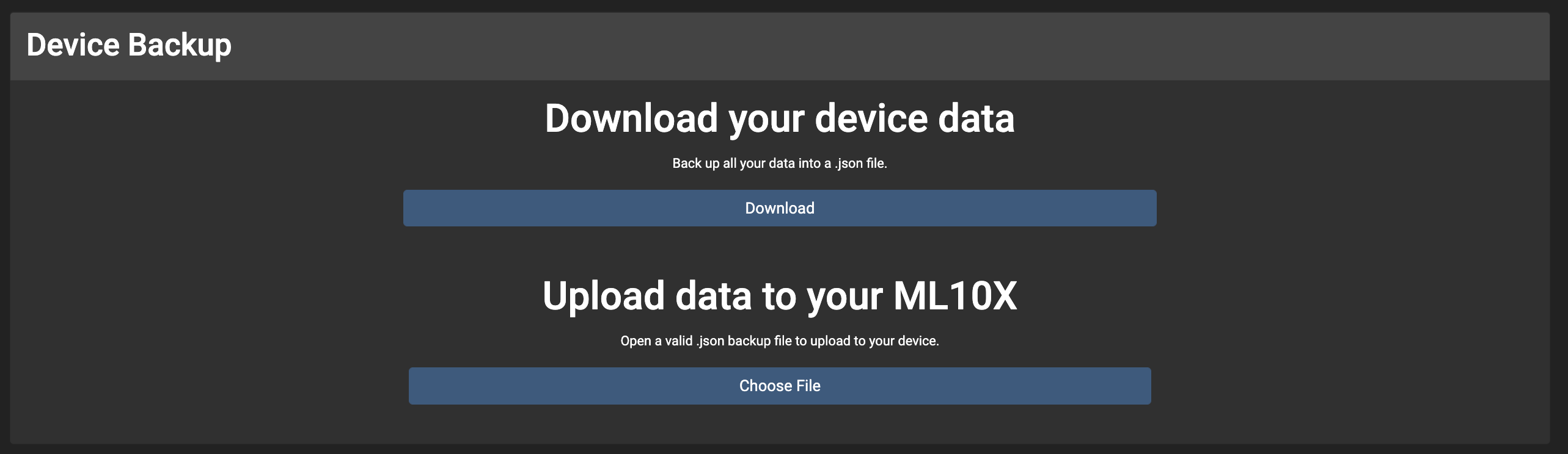
Backing up your ML10X
In the Editor, you can backup and restore your device.
Native Integration with Morningstar MIDI Controllers
There is a ML10X Message Type in the Morningstar Editor for the MC3 / MC6MKII / MC8 to let you configure what you need without having to send CC messages.
Set Loops (simple mode only)
Sets the status of all the loops in the ML10X. Selected loops will be engaged, while non-selected loops are bypassed.
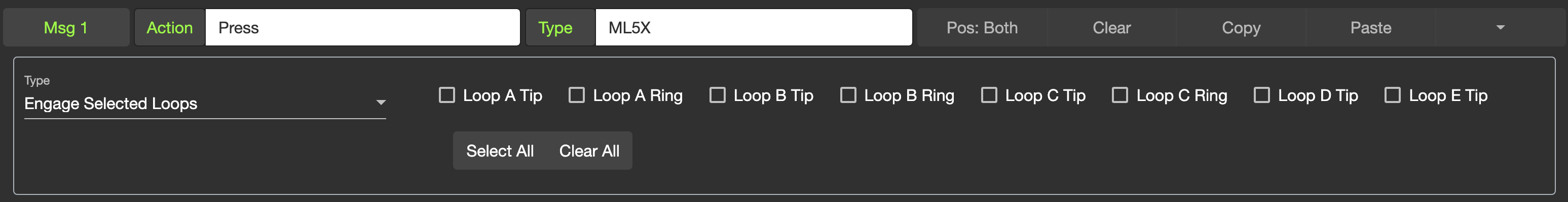
Engage Selected Loops (simple mode only)
Engages the selected loops in the ML10X.
Bypass Selected Loops (simple mode only)
Bypasses the selected loops in the ML10X.
Toggle Selected Loops (simple mode only)
Toggles the selected loops in the ML10X. If a selected loop is bypassed, it will become engaged. If a selected loop is engaged, it will become bypassed.
Scroll Up
Scroll up on the ML10X
Scroll Down
Scroll down on the ML10X
Select Preset
Selects a preset in a specific bank
MIDI Implementation
Program Change messages
PC 0 - 127 recalls Presets 0-127 in the ML10X. If you want to recall a Preset in a different bank, you will need to send a Change Bank Control Change message first, before sending the PC message to select the Preset.
Control Change messages
Loop specific messages will only work when the Preset is in simple mode.
Function | CC# | Value |
|---|---|---|
Change Bank | 0 | 0-3 |
| 4 | 0-63: Bypass, 64-127: Engage |
Scroll Up | 5 | any |
Scroll Down | 6 | any |
Mute | 7 | any |
Unmute | 8 | any |
Toggle Mute/Unmute | 9 | any |
| 10 | 0-63: Bypass, 64-127: Engage |
| 11 | 0-63: Bypass, 64-127: Engage |
| 12 | 0-63: Bypass, 64-127: Engage |
| 13 | 0-63: Bypass, 64-127: Engage |
| 14 | 0-63: Bypass, 64-127: Engage |
| 15 | 0-63: Bypass, 64-127: Engage |
| 16 | 0-63: Bypass, 64-127: Engage |
| 17 | 0-63: Bypass, 64-127: Engage |
| 18 | 0-63: Bypass, 64-127: Engage |
| 19 | 0-63: Bypass, 64-127: Engage |
| 20 | 0-127 |
| 21 | 0-127 |
| 22 | 0-127 |
| 23 | 0-127 |
| 24 | 0-127 |
| 25 | 0-127 |
| 26 | 0-127 |
| 27 | 0-127 |
| 28 | 0-127 |
| 29 | 0-127 |