
MC6 PRO
To download a PDF copy of this manual, print this page and select Save as PDF.
Foreword
Welcome to your MC6 PRO MIDI Controller. With this, you are able to control any device that accepts MIDI, regardless of brand or model. Each switch on your Morningstar controller can be programmed to perform any function you want.icons
We pride ourselves on making the easiest-to-use programmable MIDI controllers on the market. If you have any questions that this manual cannot answer, please send us an email at help@morningstarfx.com. We are happy to help.
Power Requirements
You can power your MC6 PRO in any of the following ways.
9-12V DC (centre negative) Power Supply
Connect a 9-12V DC centre negative power supply to the power input of the MC6 PRO.
The MC6 PRO requires at least 350mA of power at 9VDC.
More power is required if you are using the USB Host port to power other devices.
If you are NOT using the TRS Relay ports and USB Host port, 250mA is enough.
DO NOT USE MORE THAN 12V as that will damage the device.
Phantom Power (9-12v AC or DC)
Connect a 7-pin MIDI cable to the MIDI Out port of the MC6 PRO. Phantom power can be supplied to the MC6 PRO through pins 6 and 7 of the MIDI OUT port. When receiving DC power via phantom power, polarity does not matter. Phantom power that is received is chained to pins 6 & 7 of the MIDI IN port as well, allowing you to power other devices connected to it.
USB Power
Connect a USB cable from your computer, mobile device, USB adaptor or power bank to the MC6 PRO. The MC6 PRO is capable of being powered fully by USB.
Connections
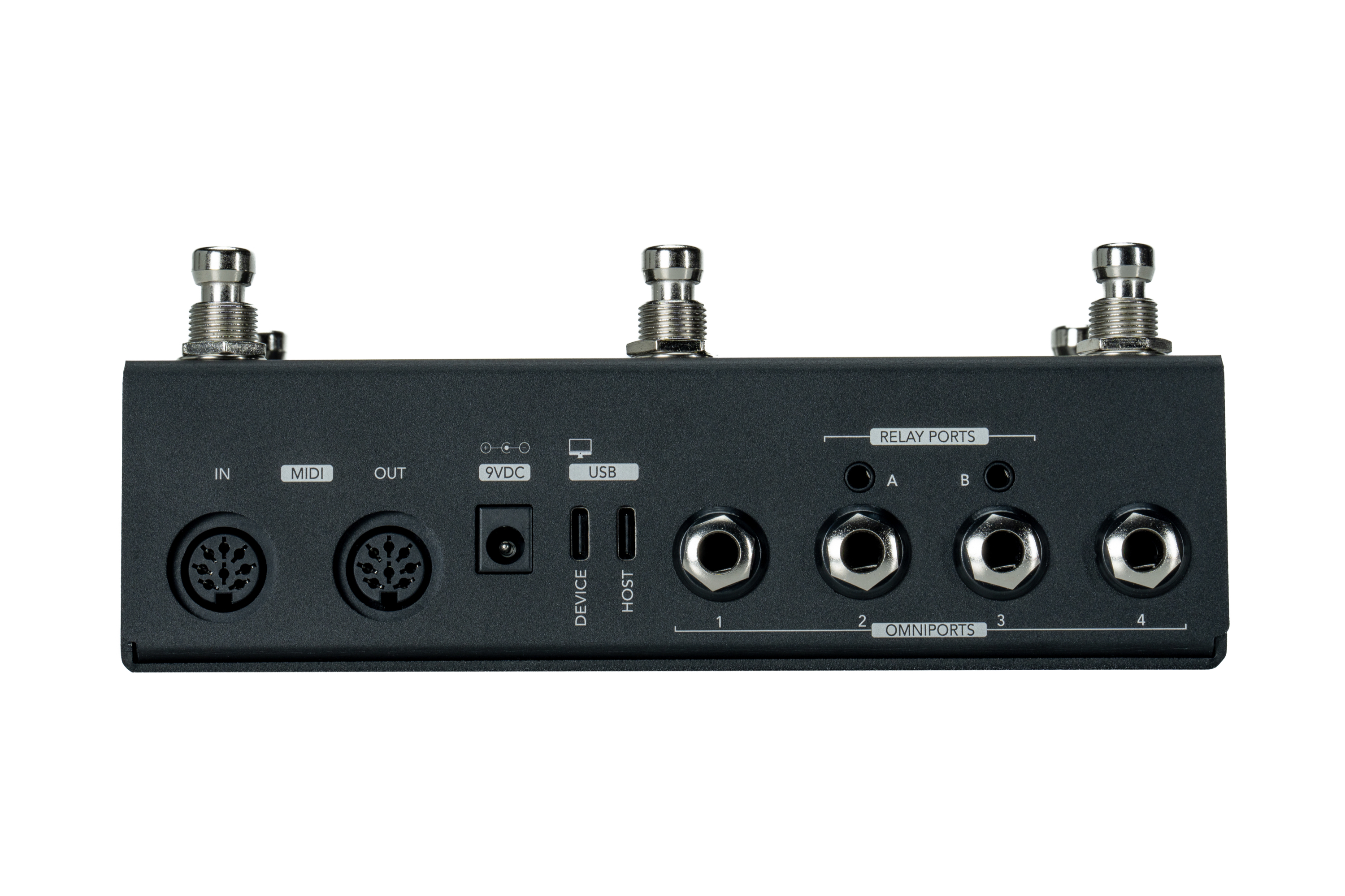
MC6 PRO I/Os
DIN5 MIDI In
Where the MC6 PRO receives MIDI messages from other MIDI devices.
The MC6 PRO can receive MIDI messages via its MIDI IN port and relay them out through its MIDI outputs (all MIDI message types) and USB port (only PC, CC, Note and MIDI Clock) .
DIN5 MIDI Out
Where MIDI data is sent from the MC6 PRO to other devices. Use a standard 5-pin MIDI cable. To phantom power your MC6 PRO, you can also use a 7-pin cable if you have a device that provides phantom power via pins 6 & 7.
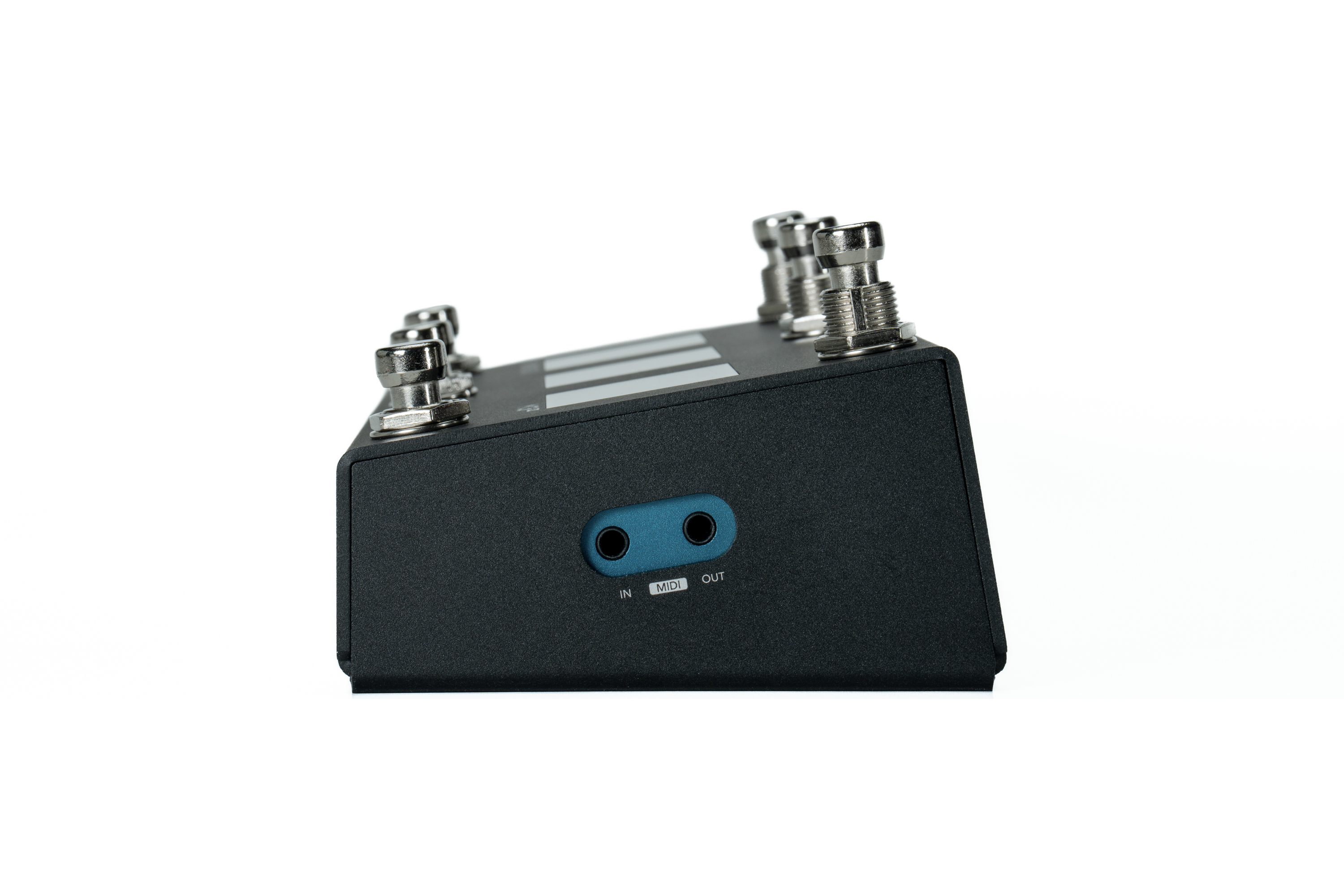
3.5mm Type A TRS MIDI Ports
3.5mm TRS MIDI In
Similar to the DIN5 MIDI IN port. MIDI Clock messages are not processed in this port. Only the DIN5 MIDI IN port is optimised to handle MIDI Clock messages.
3.5mm TRS MIDI Out
Similar to the DIN5 MIDI OUT port.
USB Device
Connect this USB port to your USB host devices, such as your computer or tablet.
This port connects to the computer to access the Editor.
Send and receive MIDI via USB. This allows you to control your DAWs, plugins and other music software. All Morningstar controllers are USB class compliant devices and compatible with Windows, macOS, Android and iOS.
As the USB Device port is a high speed USB port, it will not work with the CME WIDI uHost which only accepts full speed USB devices. The WIDI uHost can still be used with the USB Host port on the MC6 PRO.
USB Host
The MC6 PRO comes equipped with a USB Host port to allow you to control other USB MIDI devices. The Host port is capable of both sending and receiving MIDI. You can use a USB hub to connect and control up to 4 USB MIDI devices. You can also connect a computer keyboard to the USB Host port to give you control over the MC6 PRO. If connecting and powering multiple USB devices via the host port, you will need to use a powered USB hub.
Not all USB Hubs are compatible. It is not possible for us to advise which hub will or will not work. Generally, hubs with added functions besides USB, like HDMI or SD Card functionalities, will not work.
When connecting a USB Device to the USB Host port, the USB Device may be drawing power from the USB Host port. If so, there will be increased power requirements for the MC6 PRO. Please ensure that you are supplying your MC6 PRO with adequate power.
3.5mm Relay Ports
The 2 Relay Ports allows you to do Tip to Ground / Ring to Ground switches for other devices. This ports can be controlled via the Relay Interface message type.
The default startup position of the Relay Ports can be set in the device menu.
Press D+F to enter the menu, navigate to
Edit Global Config.Scroll all the way down and you’ll see a
RelayA T/RandRelayB T/Rsetting.NO/NOmeans tip and ring defaults to Normally Open on start up.NO/NCmeans that Tip is Normally Open while Ring is Normally Closed.
9VDC
Where the MC6 PRO receives 9-12V DC center negative power.
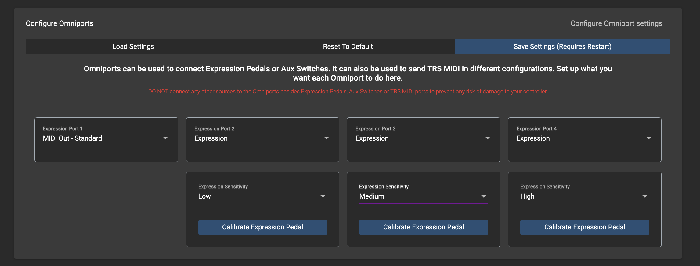
Omniports 1-4
Omniports are multi-function ports found on our MIDI controllers. Each port can be configured to work as any of the following:
TRS MIDI Output (configurable to send via the tip or ring to suit most pedals) or
TRS Expression Pedal Input or
TRS Aux Switch Input (up to 3 switches per port)
You should only use stereo cables. Using Mono cables will cause the device not to work as intended.
Please note that these ports cannot be used to control functions like amp switching, sending analog tap tempo or for Control Voltage. You should only be connecting expression pedals, aux switches and MIDI devices to these ports.
Some Chase Bliss models are not compatible with the Omniports, as they require the Tip to be completely left floating. The solution for this is to
Make a custom cable with the Tip disconnected, and then use the Ring Active Omniport MIDI Out setting.
Use the Stereo to Mono adaptor. Connect the Stereo TRS side to the Chase Bliss MIDI Input, and the Mono Ring side to the Omniport, and then send MIDI on Tip Active.
The Omniport MIDI OUT setting may not work with some MIDI devices due to the over-voltage protection we had to use to protect the processor. So far, these devices have been reported to not work with the Omniports:
Jackson Audio Golden Boy
Jackson Audio Bloom
Jet Pedals Lamb
Boss ES-5
Boss RC-5
We recommend that you use the DIN5 or 3.5MM TRS MIDI OUT, or use a MIDI Box, for these devices.
Applying power to the Omniports may damage your Morningstar controller.
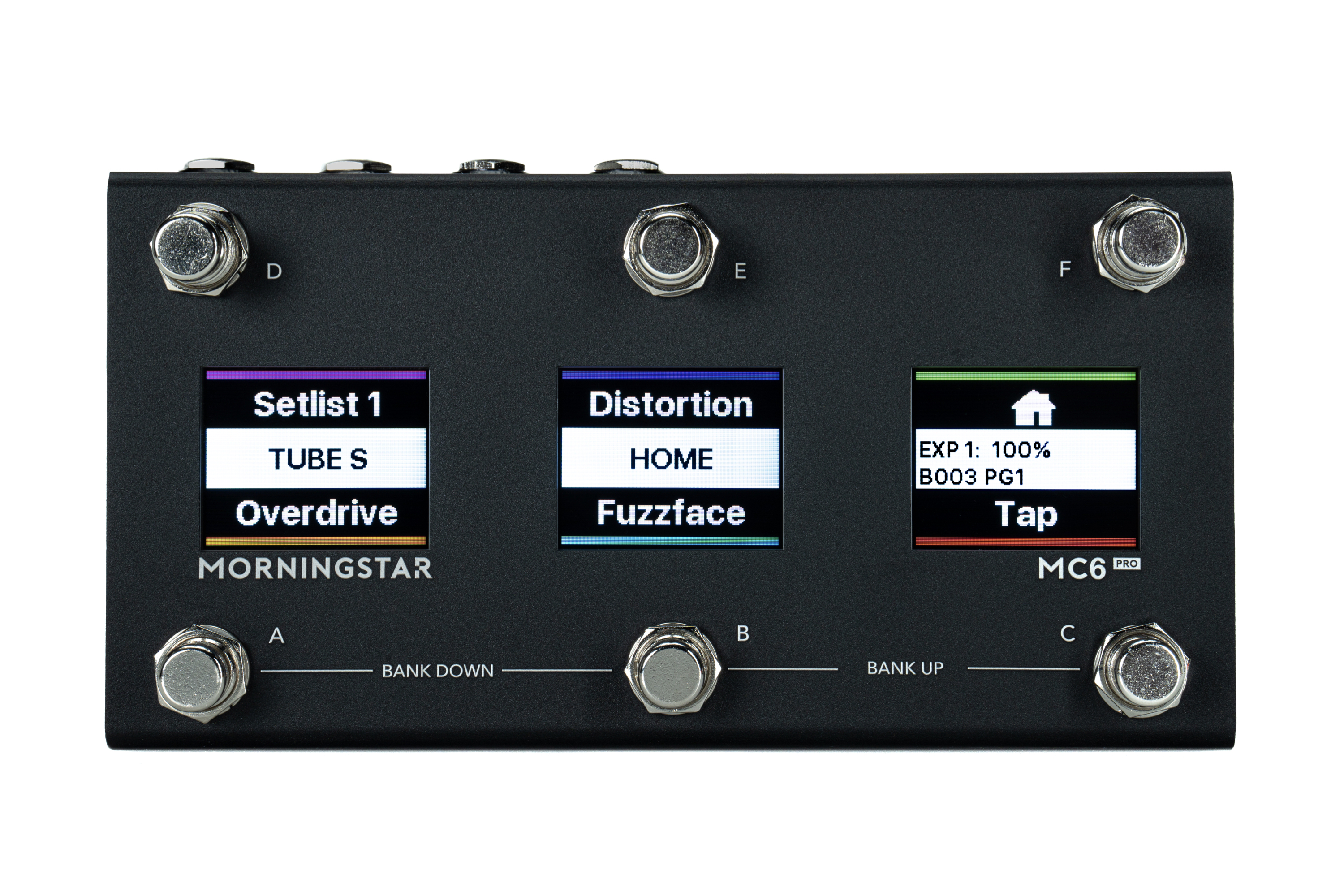
Navigation
Front Panel
The MC6 PRO has 6 foot switches A to F. Each switch corresponds with the text closest to it on the LCD display. Each switch on your Morningstar controller can send any combination of up to 32 different MIDI messages of your choice. By default all switches are EMPTY and not programmed to send any MIDI messages. It’s up to you to decide what you want!
Preset Short Names – The “EMPTY” text you see are the default short names given to unused switches. You can give each switch any name you want, so you always know what it does before you press it.
Banks, Pages and Presets
Banks
The MC6 PRO has 128 banks, each containing 24 switch presets and 4 expression pedal presets.
To bank up, press switches [B+C]. And to bank down, press [A+B]. Holding down either of these switch combinations will continuously scroll up/down through the banks.
Pages
The presets in each Bank are split into 4 pages:
Page 1: A-F
Page 2: G-L
Page 3: M-R
Page 4: S-X
You can scroll up and down the pages with switches [D+E] and [E+F]. The page toggle message types and page toggle function in the editor will allow you to toggle between Page 1 and 2 only.
Presets
Each preset can be programmed to send 32 different messages of your choice. With 16 different MIDI channels, each preset is capable of controlling up to 16 different MIDI devices at once.
The flow chart below shows you an overview of the MC6 bank and preset architecture.
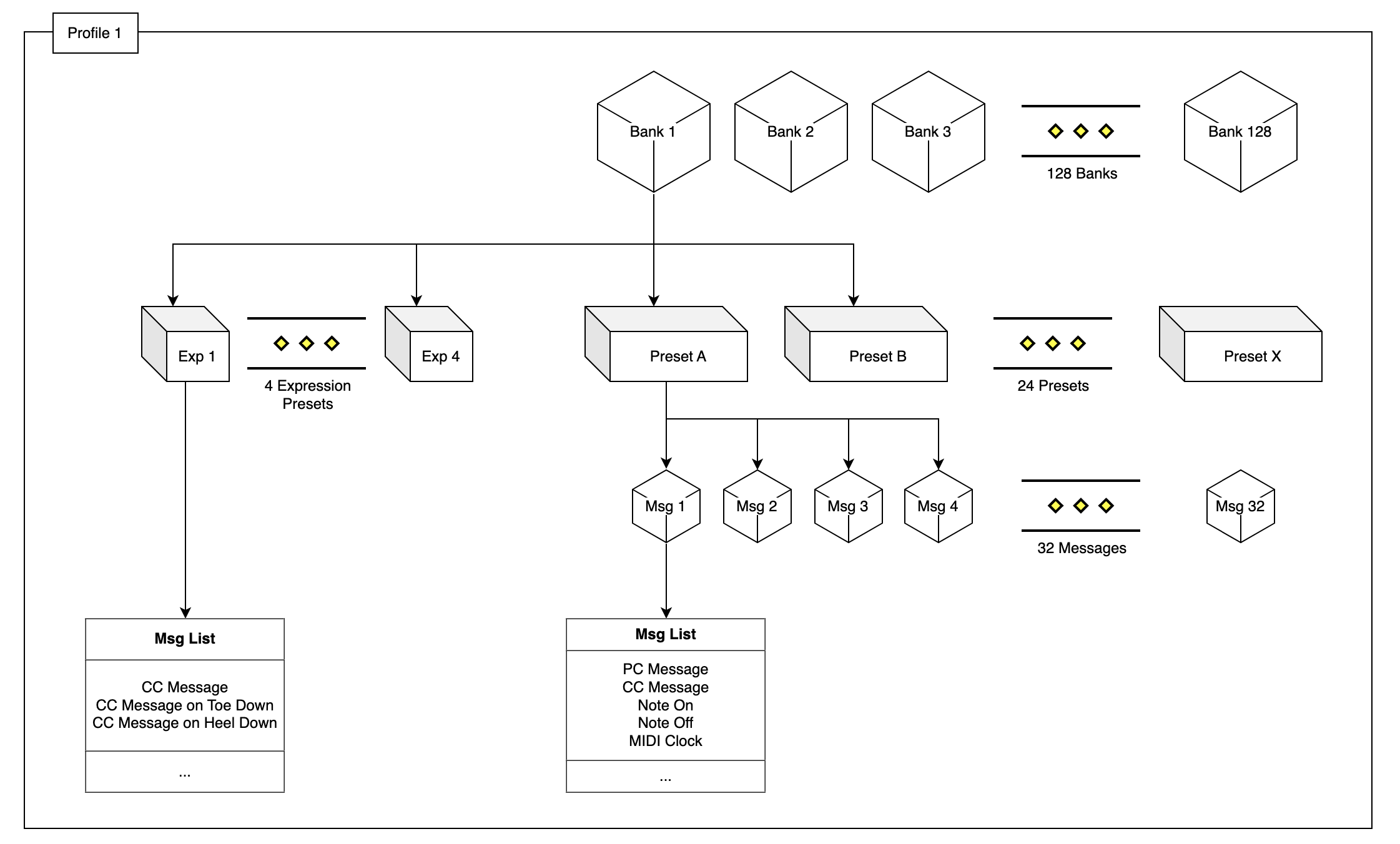
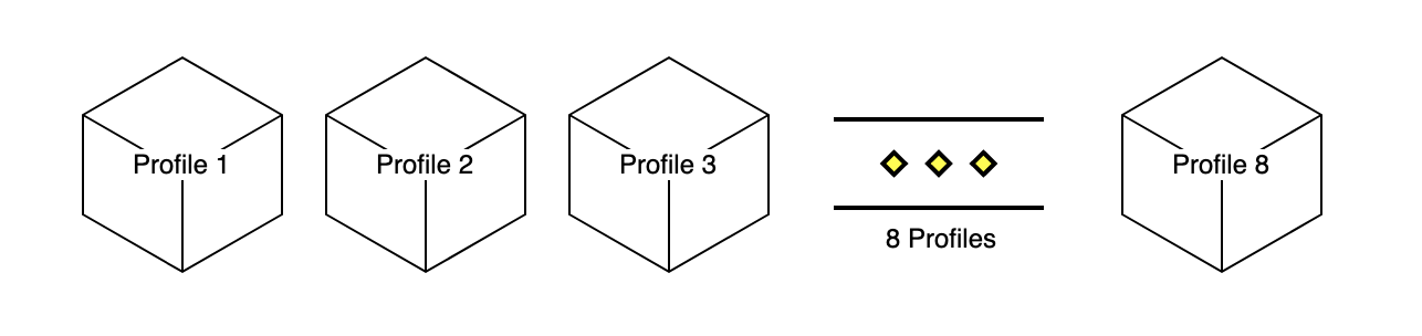
Profiles
On top of the Banks, are Profiles. The MC6 PRO has 8 profiles. Each profile gives you access to a different set of 128 Banks. These profiles are completely independent and it is not possible to interact between profiles (i.e. you cannot engage a preset in Profile 2 from Profile 1, or program a preset to jump from Profile 1 Bank 1 to Profile 2 Bank 2).
You can only change the Profile via the Menu in the controller.
Press switch
D+Fto access the menu.Navigate to
Select Profileand select the new profile you want to use
Banks
Overview
Banks consists of 24 Presets. The presets are organised into 4 pages, giving you access to 6 Presets on each. Each switch on the MC6 PRO is mapped to one Preset, depending on the page it is in.
Aside from Presets, Banks are capable of executing up to 32 messages on a Bank event such as On Bank Enter or On Bank Exit.
Concepts
Bank Attributes
Bank Name
Displayed on LCD2
To display longer text, use the newline character \n to break the name into 2 lines.
Description
Displayed on LCD1. When the Display description is enabled, the Bank Description will be shown instead of the Preset Short Name.
Clear Preset Toggles
If enabled, the bank will clear the toggle state (reset to Position 1) of all Presets in the bank except the last engaged Preset. This is useful if you only want one Preset to be in Toggle Position 2 at any one time, to indicate which Preset is active.
Bank Presets
You can execute messages on a Bank Event. For example, you can send a PC message when you enter a specific Bank, and send a different PC message when you exit that Bank. You can do this with multiple messages as well, sending different sets of messages when you enter or exit a bank.
Presets
Overview
A preset is any combination of MIDI messages/commands that you program a switch on the MIDI controller to send. Each Preset can contain up to 32 messages/commands.
Concepts
Preset Attributes
Long Name
Displayed on LCD1 when a Preset is engaged.
To display longer text, use the newline character \n to break the name into 2 lines.
Short Name
Display on each LCD to the closest switch that engages the Preset.
Background Color
The color for the background of the Short Name. Available for each state (Position 1, Position 2, Shift).
Text Color
The Short Name text color. Available for each state (Position 1, Position 2, Shift).
Strip Color
Color label for each Preset. Available for each state (Position 1, Position 2, Shift).
Preset States
Overview
A Preset has 3 states. It can send specific messages based on the state it is in. The states are:
Toggle Position 1
Toggle Position 2
Shift Position
By default, a Preset is always in Position 1.
On the MC6 PRO, you can program a short name, long name, text color, background color and strip color for each state.
Toggling Presets
A Preset can be toggled between Toggle Position 1 and Position 2 by turning on the Preset Toggle setting for that Preset. When that setting is on, the Preset will toggle between Position 1 and Position 2 whenever it is engaged.
Shifting Presets
The Shift position is a temporary state that you can put the Preset in. When a Preset is shifted, only messages set to Shift will be sent. After a Shifted Preset is engaged, the Preset will return to its prior Toggle Position.
A Preset can be shifted by using the Set Toggle message type.
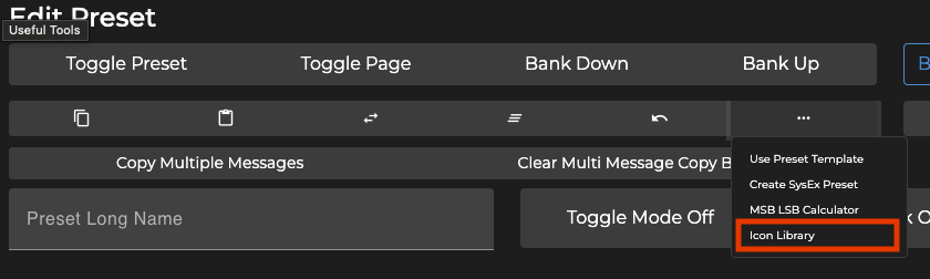
Icons
Icons can be used in Preset names by using placeholders in the name. Icons can only be printed once on the left, center or right of the text area. If you repeat the icon placeholder twice, only the first will be printed. You can view the Icon Library in the Editor, under the Preset Settings tab.
Controller Settings
Global Configuration
Dual Switch Lock
If turned on, dual switch presses are disabled. This means that pressing, for example, Switch A+B to bank down will have no effect is this setting is enabled.
MIDI Clock Persist
If turned on, MIDI Clock will continue being sent until a STOP command is given.
If turned off, MIDI Clock will stop when an event, such as a switch press, takes place.
Remember Toggle States
If turned on, the MC6 PRO remembers the toggle states of all your presets and loads them when you change banks.
If turned off, the Preset toggle states always defaults to Position 1.
Load last used bank on power up
Loads the last used bank before power off.
Ignore MIDI Clock
If turned on, incoming MIDI clock messages are ignored.
Show Preset Labels
If turned on, the Preset alphabet will be indicated on each switch.
MIDI Channel
MIDI channel for the MC6 PRO.
Switch Sensitivity
Sets the switch sensitivity for the controller. A higher sensitivity will give a faster response when a switch is pressed, but executing dual switch presses might get harder to execute.
Bank Change Delay Time
The amount of delay between bank changes. Adjust this value if you need a longer delay when scrolling through banks.
Long Press Time
The amount of time (in milliseconds) a switch has to be held down for a Long Press action to execute.
USB Virtual MIDI Ports
The MC6 PRO has 4 virtual MIDI ports when connected via USB. This setting determines how many ports it will send messages to. For example, if set to 1, only port 1 will be used, while everything else is ignored. If set to 2, port 1 and port 2 will be used, while port 3 and 4 will be ignored.
MIDI Send Delay (ms)
The amount of delay in milliseconds between each MIDI message sent. Ideally, this should be set to 0. Some MIDI devices cannot process incoming MIDI messages so quickly and might skip some messages. If this happens, a longer delay should be used, if required.
Preset Max Font Size
Sets the maximum font size for the Preset names.
MIDI Thru Matrix
Sets how MIDI Thru is handled.
Factory Reset
To reset your MC6 PRO to its factory settings, press switches [D+F]. Scroll to Factory Reset and select Reset Current Profile.
TRS MIDI Outputs - 1/4 Inch
Switchable TRS MIDI Configuration
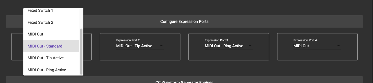
There are 3 TRS MIDI configurations available:
MIDI Out - Standard : Send MIDI via the Tip and the Ring is powered
MIDI Out - Tip Active : Send MIDI via the Tip and Ring is unpowered (floating)
MIDI Out - Ring Active: Send MIDI via the Ring and Tip is unpowered (floating)
MIDI Out - Type B: Send MIDI via the Ring and Tip is powered
The Omniports do not send System Exclusive messages
Important features to note
Safe Mode
It is possible to hang the controller if you program it wrongly. For example, if you program a Bank Preset in Bank 2 to execute an Engage Preset message that triggers Preset A, and Preset A has an Engage Preset message that triggers Preset C, and Preset C has an Engage Preset message that triggers Preset A… you get the idea. There will be an infinite loop whenever you enter Bank 2, making it impossible to edit.
To get around this, you can boot the controller in Safe Mode by holding down Switch B while booting up. While in Safe Mode, the controller does not execute any messages and you will then be able to edit the problematic Presets
MIDI Message Types
Morningstar controllers can send virtually any type of MIDI messages you need.
From standard PC (Program Change) and CC (Control Change) messages to Note, SysEx, Realtime, Keystroke commands and many more – your Morningstar controller has you covered.
For all the available MIDI message types and descriptions of what they do, please refer to our Message Type List. It gets continually updated as we add more features.
Action Types
You have the ability to send different MIDI messages by performing different actions on a switch. Such as Press, Double Tap, Release or Long Press (and more). This allows you to group MIDI messages by actions so a single switch can perform multiple functions.
For example, you can map a CC#1 message to a Press action, and a CC#2 message to a Release action. When the switch is pressed, a CC#1 message will be sent, and when the switch is released, a CC#2 messages will be sent.
For all the available Action types and their descriptions, please refer to the Action Type List.
Programming Switches
All switches on your Morningstar controller come empty by default. It’s up to you to decide what you want each switch to do. Each switch can send up to 32 different MIDI messages simultaneously.
The combination of MIDI messages a switch sends makes up a preset.
There are 2 ways you can program your switches, either by using the Morningstar Device Editor or programming on the controller itself. As the number of options is very extensive in the MC6 Pro, programming directly on the device has limited functionalities, while using the software editor will give you access to all the available parameters.
Accessing the menu
Pressing switch D+F together will open the menu. You can then use the switches to navigate around the menu system.
Expression Pedals
🎥 Watch https://youtu.be/-TNTkqh-gEE for a demo and tutorial on how to use an expression pedal with MIDI.
Expression Presets
Each Omniport is mapped to an Expression Preset. For example, Omniport 1 is mapped to Expression Preset 1, Omniport 2 is mapped to Expression Preset 2 and so on… Hence, if you have an expression pedal connected to Omniport 1, you should use Expression Preset 1.
Connecting an Expression Pedal
Before using an expression pedal, check to make sure that the Ommiport you are using is set to accept an expression pedal. You can set this in the Controller Settings.
The MC6 PRO works only with TRS expression pedals. Expression pedals fitted with 10k ohm linear potentiometers give the most accurate and smoothest response, though 10k - 25k ohm linear potentiometers will work as sell. The potentiometer wiper should be connected to the Tip of the stereo cable, while the Ring and Sleeve should be connected to the outer lugs on the potentiometer.
Calibrating your Expression Pedal
After connecting a new expression pedal, be sure to calibrate it before use. This is to set the correct heel and toe positions relative to CC values 0-127 and allow you to use the full sweep of your expression pedal. Enter calibration mode by pressing [D+F] to access the Main Menu > Edit Expression > Calibrate. You can also access this mode from the Editor under Omniport Settings.
First, put your expression pedal into heel down position, then into toe down position. Then press Save to save your settings. Once calibration is complete, MC6 PRO will automatically optimize settings to best suit your expression pedal.
Expression Pedal Sensitivity
Expression pedals not using 10k ohm potentiometers can cause jitters in the expression pedal readings. If you are experiencing this, you can lower the sensitivity of your expression pedal to eliminate the jitters.
External Aux Switches
🎥 Watch https://youtu.be/IYEjrzsaSbc for a demo and tutorial on how to add aux switches to your controller.
Connect external aux switches for more control. Under your Omniport settings, you can configure to the aux switch to behave as fully programmable switches to engage presets and controlling other functions like banking up/down
Your Aux switches will function as fully programmable switches, just like the built-in switches (sans the LCD display)
Omniport Settings
TRS Aux Switch - Your Aux switches will function as fully programmable switches, just like the built-in switches (sans the LCD display). You can map any of the MC8 presets to your desired aux switches.
You can also set your Aux switches to function as bank up, bank down, toggle page and MIDI Clock switches and more.
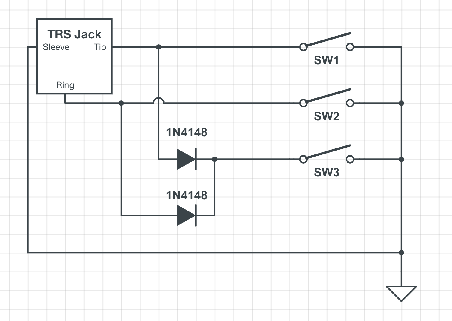
Switch schematic
The MC6 PRO requires aux switches that are wired like in the schematic below. It has to be connected to the device with a stereo cable, where the Tip is connected to the ground via a SPST Footswitch, and similar to the Ring as well. Another switch can be added to connect both Tip and Ring to ground to engage an additional preset/setting. Please refer to the schematic below.
Below are a few builders that offer such switches.
Click for link to products. We are not affiliated with them.
The footswitches need to be Momentary (non latching) and Normally Open
If you would like to build one yourself, you can refer to the following schematic:
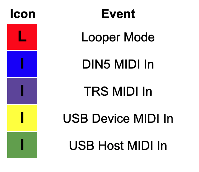
LCD Indicator Icons
The MC6 PRO flashes coloured icons on LCD3 when certain events take place.
MIDI IN ports
The MC6 Pro features multiple MIDI IN ports:
DIN5 MIDI In
3.5mm TRS MIDI In
USB Device MIDI
USB Host MIDI
With the wide array of options, certain ports are optimised for timing-critical tasks such as handling MIDI clock messages.
Handling MIDI Thru
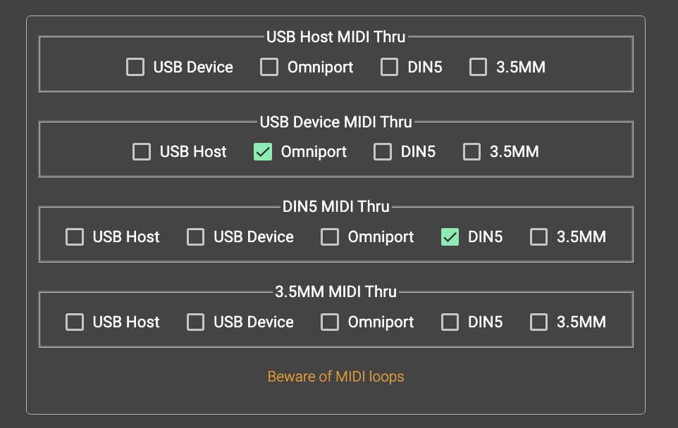
The MIDI Thru settings is available in the Controller Settings, under General Configuration. You can set the MIDI Thru output for each MIDI Input. In the image above, incoming MIDI messages from the USB Device port will be routed to the Omniports, and DIN5 MIDI Input routed to the DIN5 MIDI Output.
MIDI Message Converter
Each incoming MIDI message can be processed by the MIDI Message Converter function, under the Controller Settings. This feature allows you to process incoming MIDI messages and convert them to different MIDI messages.
Receiving MIDI Clock messages
If you need to pass MIDI Clock through from an external MIDI clock source, use the DIN5 MIDI IN port.
The 3.5mm TRS MIDI IN port will not handle MIDI Clock messages. The DIN5 MIDI IN port is optimised to handle MIDI Clock messages to ensure low jitter.
Connecting to the Editor via MIDI Bluetooth dongle
A MIDI Bluetooth dongle like the CME WIDI Jack can be connected to the DIN5 or 3.5mm TRS MIDI ports to communicate with the editor.
If you are using the CME WIDI Jack, please note that there is a “Type A/B” switch on the dongle. It is set to Type B by default, as the DIN to TRS converter cables provided by CME are Type B cables.
If you are connecting the WIDI Jack to the 3.5mm TRS MIDI ports, it needs to be set to Type A.
Dual Switch Press Functions
Dual switch press combinations allow you to control certain utility functions and access hidden presets beyond the first 16 presets.
Switches | Utility Function |
|---|---|
A + B | Bank Down |
B + C | Bank Up |
D + E | PageDown |
E + F | Page Up |
A + D | Engage Preset I |
B + E | Engage Preset J |
C + F | Engage Preset K |
MIDI Implementation
The MC6 PRO can be controlled by external MIDI controllers.
MIDI Implementation Charts
PC Messages
PC messages will change the banks on the MC6 PRO, where a PC#0 message will engage Bank 1, and PC#1 message will engage Bank 2, and so on.
MIDI PC Implementation Chart
PC# | Bank |
|---|---|
0 | 1 |
1 | 2 |
2 | 3 |
. . . | . . . |
127 | 128 |
CC Messages
CC messages allow you to navigate through the MC6 PRO’s banks, engage presets and clear toggle states.
MIDI CC Implementation Chart
Function | CC# | Value |
|---|---|---|
Bank Up | 0 | any |
Bank Down | 1 | any |
Set Toggle (All) | 2 | 127 |
Set Toggle (Individual) | 2 | 0 = Preset A . . |
Clear Toggle (All) | 3 | 127 |
Clear Toggle (Individual) | 3 | 0 = Preset A . . . |
Toggle Page | 4 | 0 = Toggle Page |
Engage Preset | 10 = Preset A . . | 0 = Do Nothing |
Set MIDI BPM (MSB 2 bits) | 5 | 0-127 |
Set MIDI BPM (LSB 7 bits) | 6 | 0-127 |
Looper Mode | 7 | 0-127 |
MIDI Clock Tap | 8 | 0-127 |
Jump to last used bank/page | 9 | 127 = Last used Bank. Execute bank presets 1 = Last used Bank/Page. Ignore bank presets |
Control Relay A Tip | 40 | 1 = Tap, Normally Open |
Control Relay A Ring | 41 | “ |
Control Relay B Tip | 42 | “ |
Control Relay B Ring | 43 | “ |
Engage Expression 1 | 51 | 0-127 |
Engage Expression 2 | 52 | 0-127 |
Engage Expression 3 | 53 | 0-127 |
Engage Expression 4 | 54 | 0-127 |
SysEx API for external applications
For more advanced usage, the MC6 PRO can also be controlled via SysEx. You can view the SysEx API here.
Using a Keyboard connected to the USB Host
A Keyboard can be connected to the USB Host port to give you enhanced control over your MC6 PRO.
Pressing the LEFT, RIGHT, UP and DOWN arrow keys allows you to bank up/down or page up/down.
Each alphabet key directly engages the corresponding Preset. For example, double tapping the A key will execute a double tap on Preset A.
Updating the Firmware
We regularly update our controllers' firmware to introduce new features, improve performance and fix bugs. Firmware .hex files are made available in our Downloads page. These files contain the data that needs to be uploaded into the MC6 PRO. There are 2 ways to do this.
Using the Firmware Updater Software
The Firmware Updater Software allows you to transfer the .hex file directly into the MC6 PRO. It is available on our Downloads page.
Using the Editor
With the MC6 PRO, it is possible to transfer the .hex file using the editor. In the Editor, there is a Firmware Update tab. In that section, you’ll need to select the .hex file and then follow the steps shown in the Editor.